

Overview
Scenario 18 simulates the trajectories of two receivers (associated with two pedestrian users) moving inside the LASSE laboratory environment, starting from opposite ends of the room and converging to a common final point. Throughout the route, each receiver represents a distinct propagation condition: one under line-of-sight (LOS) and the other under non-line-of-sight (NLOS); in the final segment, both become in direct visibility with the transmitter. This dataset was created specifically to validate a new Raymobtime feature focused on indoor simulations with antennas attached to pedestrians, replacing the traditional vehicle-based mobility model.
LASSE ROOM
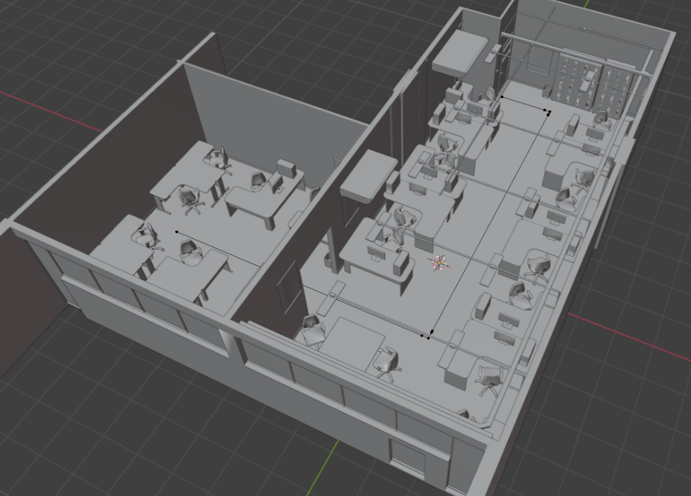
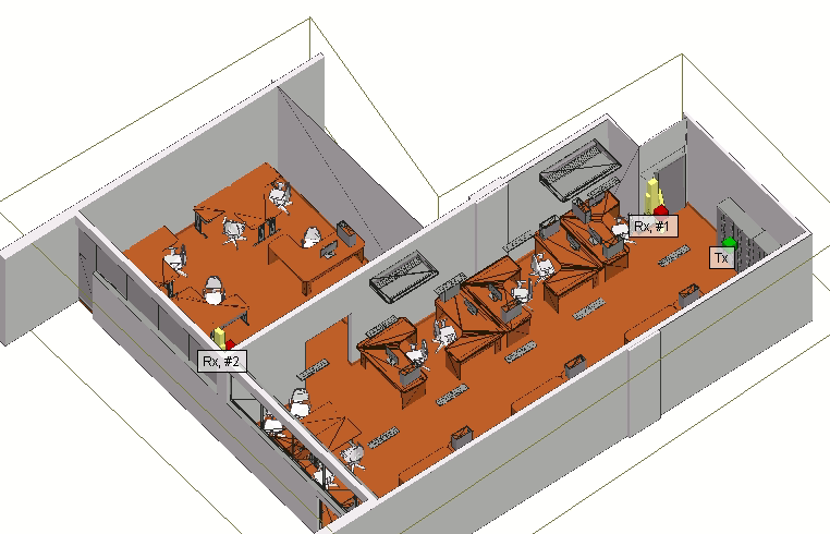
The LASSE indoor scenario models a realistic laboratory environment composed of two rooms connected by corridors openings and populated with a dense set of objects (e.g., desks, chairs, cabinets, shelves, and lab furniture). This rich clutter is intentionally included to increase fidelity with the real site, creating abundant reflecting and scattering surfaces and frequent occlusion opportunities typical of indoor deployments. A single transmitter (Tx) is placed inside the main lab area, while two mobile receivers (Rx #1 and Rx #2) represent pedestrian users carrying antenna devices.
Mobility is defined in SUMO using two independent pedestrian routes that start from opposite ends of the environment and move toward a final meeting region where both receivers eventually reach direct visibility (LOS) to the transmitter. Each route is modeled as a single-lane pedestrian path (number of lanes: 1) with a narrow effective width of 0.5 m, consistent with indoor walking corridors between furniture and structural elements. Both pedestrians move at a constant walking speed of 1.34 m/s. Route 1 has a total path length of 15.27 m, while Route 2 has a total path length of 16.5 m, yielding slightly different traversal times and spatial exposure to blockage and multipath
From a wireless-channel perspective, the environment behaves as an indoor canyon: walls, partitions, and large furniture create strong multipath through reflections and diffractions, while corners and obstructions induce transitions between NLOS and LOS conditions along the trajectories. In this scenario, one receiver is configured to predominantly experience LOS-like propagation over the route, whereas the other is designed to undergo more NLOS segments, with both converging to an LOS condition near the end of the paths. This combination of realistic geometry, dense object placement, and controlled pedestrian mobility makes the scenario representative for evaluating indoor beam management tasks such as beam tracking, blockage events, and robustness to rapid LOS/NLOS transitions.
Collected Data
The collected data was generated using the Raymobtime pipeline, which couples vehicular and ´pedestrian traffic simulation in SUMO with scene generation and ray-tracing in Remcom Wireless InSite (WI) via a Python orchestrator.
1. Ray tracing data: top 100 rays of highest received power, obtained from Wireless Insite (WI).
- Received power, time of arrival, elevation angle of departure, azimuth angle of departure, elevation angle of arrival, azimuth angle of arrival, LOS condition.
- Type data: .hdf5 of each episode
- At database .db file is possible take rays paths and interactions information.
Data Visualization
Dataset details
| 3D scenario | LASSE indoor |
| Frequency | 60 GHz |
| Number of receivers and type | 2 Mobile Pedestrian |
| Number of episodes | 1 |
| Number of scenes per episode | 800 |
| Time between scenes | 100 ms |
| Number of runs | 800 |
Simulation details
- Traffic parameters (Simulator of Urban Mobility)
| Number of lanes | 1 |
| Vehicles | Pedestrian |
| Lengths (m) | 0.5 |
| Heights (m) | 0.4 |
| Average speed (m/s) | 1.34 |
| Sampling period (s) | 0.1 |
- Elements and materials (WI)
| Elements | Material |
| Blackout Tril | PEC Metal |
| Chair | One-layer dieletric Permittivity = 2.5 Conductivity = 0.015 Thickness = 3 |
| Floor | ITU Floorboard 60GHz |
| Lamps | PEC Metal |
| Door | PEC Metal |
| Loockers | PEC Metal |
| Table | PEC Metal |
| Monitors | PEC Metal |
| Outdoor | PEC Metal |
| PC | PEC Metal |
| Spliters | PEC Metal |
| Walls | ITU Layered drywall 60GHz |
| Window Frame | Pem Metal |
| Window Glass | ITU Glass 60GHz |
| Table | ITU Wood 60GHz |
| Pedestrian | Human Dry Skin 60GHz |
- Transmitter details (WI)
| Number and type | 1 Fixed |
| Antenna type | Isotropic |
| Input power | 0 dbm |
| Position (x,y,z) (m) | 1.79, 7.18, 2.0 |
- Receiver details (WI)
| Number and type | 2 Mobile |
| Plataform type | Point |
| Antenna type | Isotropic |
| Noise figure | 3 dbm |
- Ray tracing configuration (WI)
| Propagation model | X3D |
| Number of reflections | 6 |
| Number of transmissions | 0 |
| Number of diffractions | 1 |
| Number of rays | 100 |
| Ray spacing | 1° |
- Diffuse Scattering configuration (WI)
| Diffuse scattering | Habilited |
| Model | Lambertian |
| Max reflections | 2 |
| Max transmissions | 0 |
| Max diffractions | 1 |
- Signal Information (WI)
| Signal type | Sinusoid |
| Frequency | 60 GHz |
| Bandwidth | 1 MHz |
Wireless Insite:
The LASSE scenario used at simulations corresponds to a 3-D model that is part of Wireless insite examples.
The simulation was realized at wireless insite 3.3
Download
Files and folders explanation
📁 1. s000_episodedata — Objects and rays database (db)
Database with tables where episodes, scenes, mobile objects and receivers are related.
Tables:
[episodes, scenes, objects, rays, receivers]
Util information at tables:
– Rays (table)
[id, departure_elevation, departure_azimuth, arrival_elevation, arrival_azimuth, path_gain, time_of_arrival, interactions, receiver_id]
– Receiver (table)
[id, total_received_power, mean_time_of_arrival, object_id]
– Object (table)
[id, name, scene_id]
– Scene (table)
[id, episode_id]
📁 2. ray_tracing_data_s000_carrier60GHz/ — Rays Information (HDF5)
The ray-traced data is stored in HDF5 format using a four-dimensional structure:
Structure:[number of scenes, number of TX–RX pairs, maximum number of rays, number of stored parameters]
Each ray contains:
- Received power (dBm)
- Time of arrival (seconds)
- Elevation angle of departure (degrees)
- Azimuth angle of departure (degrees)
- Elevation angle of arrival (degrees)
- Azimuth angle of arrival (degrees)
- LOS flag: 1 = LOS, 0 = NLOS
This data enables high-fidelity reconstruction of multipath behavior, reflections, diffractions, and critical LOS/NLOS transitions.
📁 3. documentation/ — README and Citation Information
This folder contains:
- Dataset README
- License and usage rules
- Citation generator references
- Links to related academic papers
- Change logs or updates